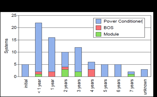
During the first 10 years in service, the chance of failure within a PV system is approximately 10%. Inverters and other electronic devices account for 85% of all those PV system failures. Only about 1 in 2000 modules will fail during their warranted 25-year life. The system components most likely to fail are the ones with complex electronic circuitry. The graph below identifies this type of equipment as Power Conditioning; it includes monitoring equipment, inverters, PV optimizers & other DC to DC conversion devices. The causes of failure are from manufacturing defects, improper installation, operating stress and accidents. The first of these is out of the control of the installation and maintenance contractors and the last of these, accidents, is usually outside of their control; the second two, improper installation and operating stress, are not.
Failing Power Conditioning equipment will perform at a lower efficiency than warranted; failed equipment will stop performing its function. Failures due to improper installation and operating stress are both avoidable. Causes of these failures are: Inadequate wire terminations, undersized conductors, environmental conditions that are outside of the equipment rating, inadequate protection from surge voltage and inadequate protection from physical damage. Once the equipment is operational, an infrared camera can detect damage that is occurring from heat at the terminals and inside the equipment. Terminal temperatures should vary no more than 3°C from one to another under the same current load. The internal parts of the equipment should not exceed the max rated temperature listed by the manufacturer. If equipment is failing but still operating, the conversion efficiency can be measured by reading the (Volts x Amps) at the input and output of the equipment. The difference should be no less than the rated efficiency of the equipment. Test six months after installation and then annually thereafter.
Module failures get most of the attention since they don’t usually fail completely but continue to function at a lower output; the causes of failure are numerous. A module is considered failed when one of the following occurs: Breakage, delamination, burned solder joints, browning of a PV cell due to overheating, bad bypass diode or degradation in performance beyond the warrantied percentage. These are covered by the manufacturer’s warranty; depending on the failure mode, proof of failure can be verified with a standard photograph, infrared photograph or by inspection test with a calibrated meter such as an I-V curve tracer. A module is considered failing if it performs lower than other modules of comparable design and type. An IR camera may detect hot spots on PV cells that decrease performance – an IV curve tracer can determine whether the module is operating below its warranted performance. Test with an IR camera annually, and with an I-V curve tracer for large commercial projects.
The most common long-term failures are: Hot spots due to manufacturing defects in the cells, hot cells caused by high current flow in a de-energized state, potential induced degradation (PID) caused by leakage currents to earth ground, low cell conversion rate due to cracks within the cell, delamination caused by extreme heat and humidity and current loss due to shorts (shunting) between cells where the module substrate is damaged by wind and dust or other natural causes. An I-V curve tracer and an IR camera can identify most of these problems. For residential and some commercial projects module level monitoring will identify problems; it is easy to compare each module performance to the others around it.
The other failure category shown in the graph is balance of system components (BOS). This is generally all the wiring, conduit, switchgear, junction boxes and module support structure. Failure is usually due to improper wire sizing or termination, galvanic corrosion with incompatible metals, materials installed in environments beyond their rating and improperly installed components. Prevention of failure includes testing conductor resistance before startup, capturing IR images at terminals when equipment is operating, measuring resistance to ground on all grounded metal parts and making a visual and torque inspection of all physical and electrical connections. Test six months after installation and then annually thereafter.
The most valuable tool for inspecting PV system performance is a module level monitoring system; most new residential and small commercial projects now have this level of monitoring. The next best tool is an IR camera; since there are now IR devices that connect to smart phones this is a very affordable option. The next best tool is an AC/DC volt-amp meter. You can take readings on the input and output of any equipment and determine the loss factor for that piece of equipment. If you are working on commercial systems, you will want a conductor resistance tester to measure the conductor insulation resistance to leakage currents at the maximum operating voltage. The I-V curve tracer is unnecessary for residential and small commercial projects. They are usually required for large commercial and utility scale projects.
Kelly Provence
Solairgen School of Solar Technology
IREC Certified Master PV Trainer
NABCEP Certified Professional Installer

